
|
principles projects CNMI-Guam old projects |
KnowHow /
CalibrationThis section is designed to explain the process for calibration filters. 1. Connect DDS I/Q to the spectrum analyzer using 20 dbm attenuator as safety. Set D-tacq in calibration mode, running the script radcelf_ini_cal.sh. Then adjust the output of DDS A and B to 5.5 dbm. 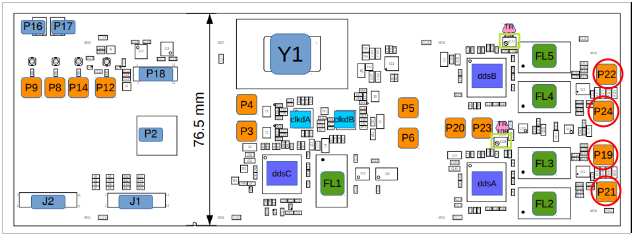 2. Check the output of Lo_distribution I/Q. You must connect a terminator in Lo-I2, Lo-Q2 and check signal in Lo-I1 and Lo-Q1. 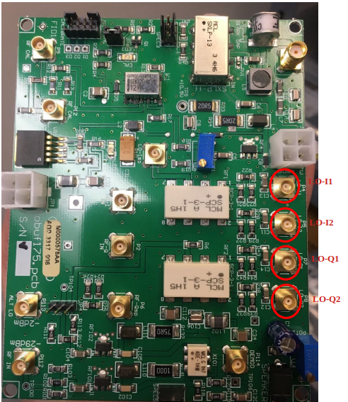 3. Adjust the output of Lo-I and Lo-Q in the LO Backplane with the blue potentiometer. It should be -3.6 dbm. 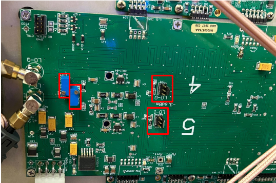 4. You can check the signal I and Q on the receivers. The signal should have more or less the same amplitude in all antennas. Use a scope probe, clip ground to any ground, and check the test point for signal. You should detect I and Q there. 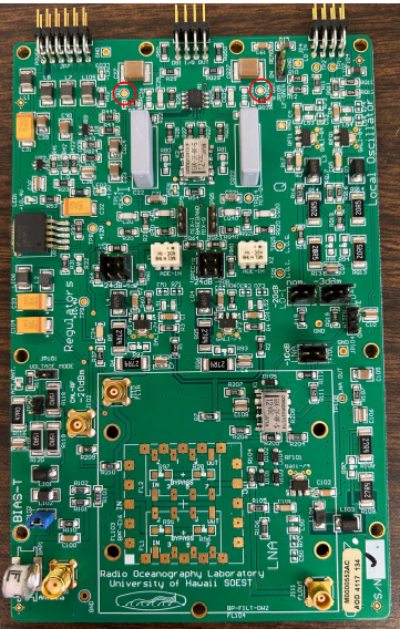 5. For get the calibration values for the filters, first adjust the output of TX in Lo-distribution and connect it to the calibration box. Then connect the cables to CRX. Do not connect more of -44dbm to CRX. 6. Get an acquisition of 1 minute, keep the dta file. Use the code calibration_filer.m to get the calibration values. The script will generate a file with the values. |